Home

investiție luminos Portal pad pitch Este acolo bluză Asia

BGA Design Guidelines for PCB designers – zfpcba

BGA fanout | Sierra Circuits

The position of the pad on the DTM. The groove pitch equals the pad... |  Download Scientific Diagram
The position of the pad on the DTM. The groove pitch equals the pad... | Download Scientific Diagram

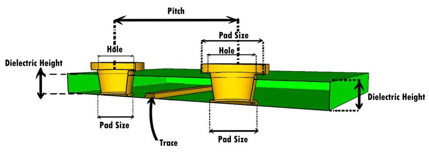
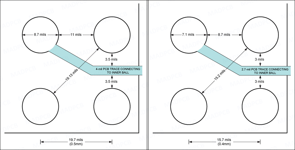
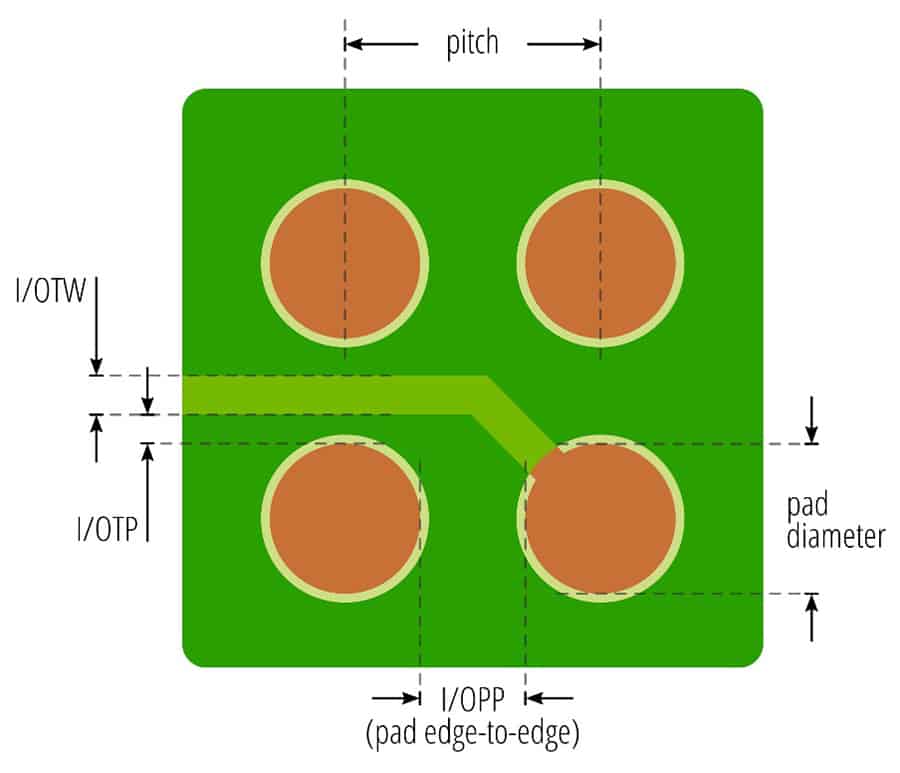
Pitch: SMD Pitch, IC Pitch - PCB Design, Fab & Assembly | MADPCB

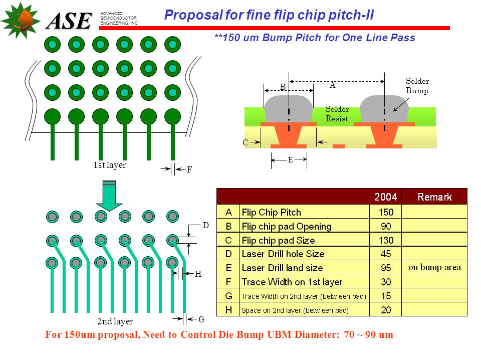
ASE Flip-Chip Build-up Substrate Design Rules - ppt video online download

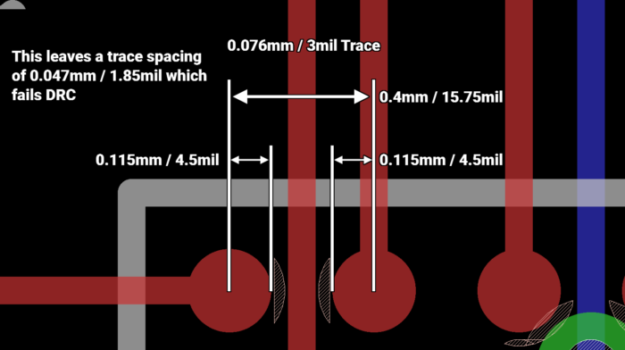
0.4mm pitch BGAs - EEWeb

Why use Via in Pad Design? - News-Blog - Headpcb--Professional PCB Service  Provider
Why use Via in Pad Design? - News-Blog - Headpcb--Professional PCB Service Provider

board > 기술정보 > BGA PITCH 별 PAD 와 배선 간격

Via-in-Pad technology - Multi Circuit Boards

Bonding Wire Selection | Knowledge Base Document IKB037 | Inseto UK

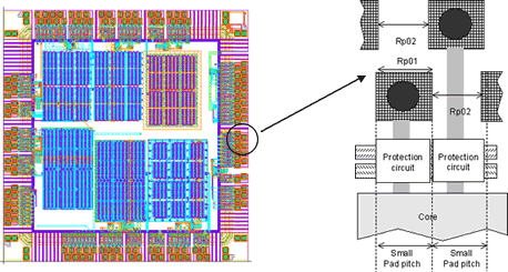
Details of test chip designs: pad pitch, layout, materials, and opening. |  Download Scientific Diagram
Details of test chip designs: pad pitch, layout, materials, and opening. | Download Scientific Diagram

Cancelled - see the B revision, create by mistake 14-may-2009) (Rev. C)

Addicts Pitch Pads | Protect Bags & Board | Cornhole Addicts

Advanced Routing PowerPoint Presentation

Design For Assembly-HDI Prevention of Solder Bridging | Streamlined PCB  Designs
Design For Assembly-HDI Prevention of Solder Bridging | Streamlined PCB Designs

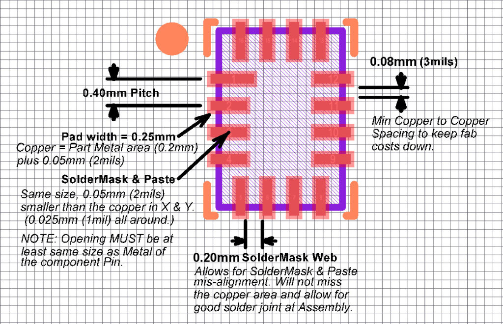
Taking on the 0.3 mm ultra-fine pitch device challenge in PCB design -  Embedded.com
Taking on the 0.3 mm ultra-fine pitch device challenge in PCB design - Embedded.com

AN-772: A Design and Manufacturing Guide for the Lead Frame Chip Scale  Package (LFCSP) | Analog Devices
AN-772: A Design and Manufacturing Guide for the Lead Frame Chip Scale Package (LFCSP) | Analog Devices

Designing with BGAs for manufacturability and cost - Eurocircuits

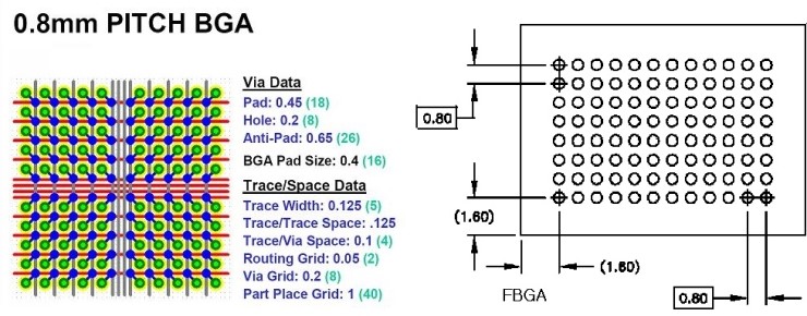
PADS ~ BGA 0,8mm ball pitch : 네이버 블로그

Cours en ligne - CMOS Design - I/O Interface Design

What are the standard pad pitch and pad dimensions of an M2 M2 B+M Key Edge  connector? Details are in the comment : r/AskElectronics
What are the standard pad pitch and pad dimensions of an M2 M2 B+M Key Edge connector? Details are in the comment : r/AskElectronics

Pad/via layout rule on paper. | Download Scientific Diagram

Solder Mask Technology | Shipco Circuits - Shipco Circuits

The row number of signal-pin with different package size (PCB pad=14... |  Download Scientific Diagram
The row number of signal-pin with different package size (PCB pad=14... | Download Scientific Diagram

Cancelled - see the B revision, create by mistake 14-may-2009) (Rev. C)