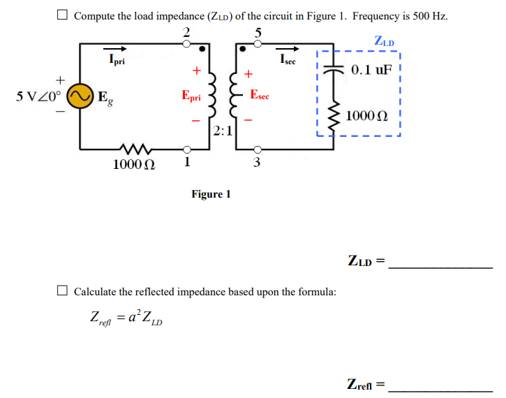
Solved Compute the load impedance (Zo) of the circuit in
Impedance matching a purely resistive load
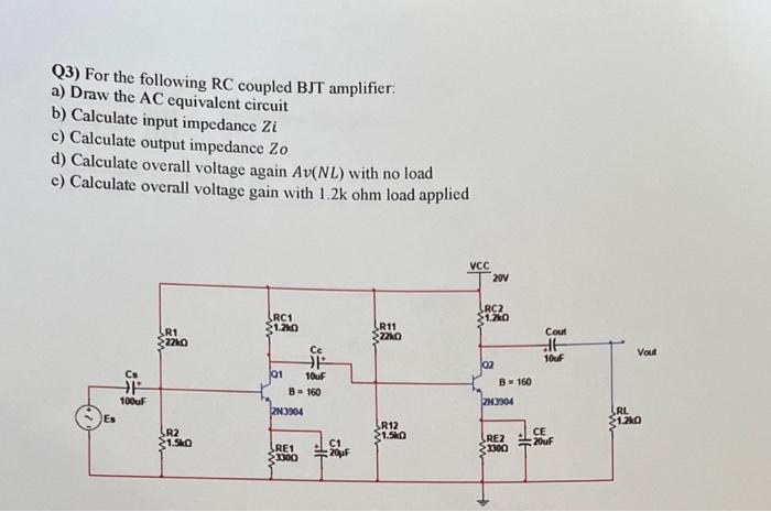
Solved Q3) For the following RC coupled BJT amplifier: a)
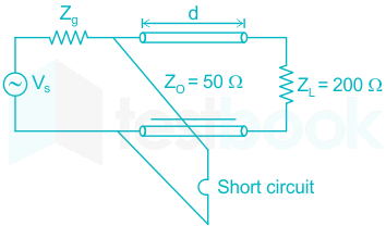
Solved] The transmission line of characteristic impedance 50 Ω
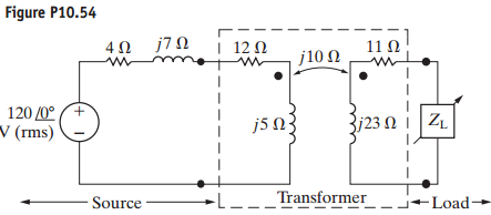
Solved) - The impedance Z L in the circuit in Fig P10.54 is adjusted for (2 Answers)
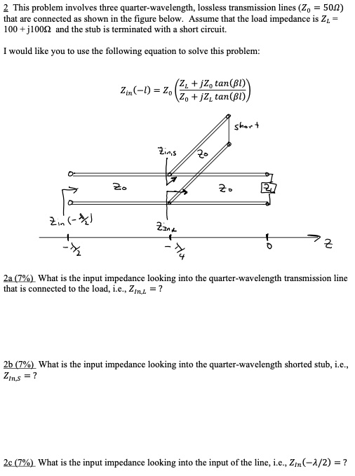
SOLVED: This problem involves three quarter-wavelength, lossless transmission lines (Z = 50) that are connected as shown in the figure below. Assume that the load impedance is Z = 100 + j100
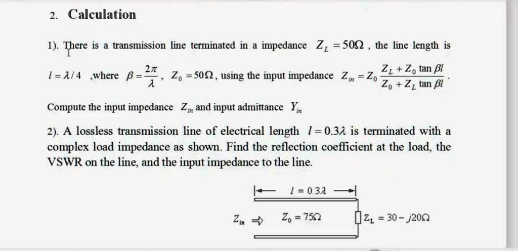
SOLVED: There is a transmission line terminated in an impedance Z = 50. The line length is Z + Z0tan(l). Compute the input impedance Z and input admittance Y. 2. A lossless
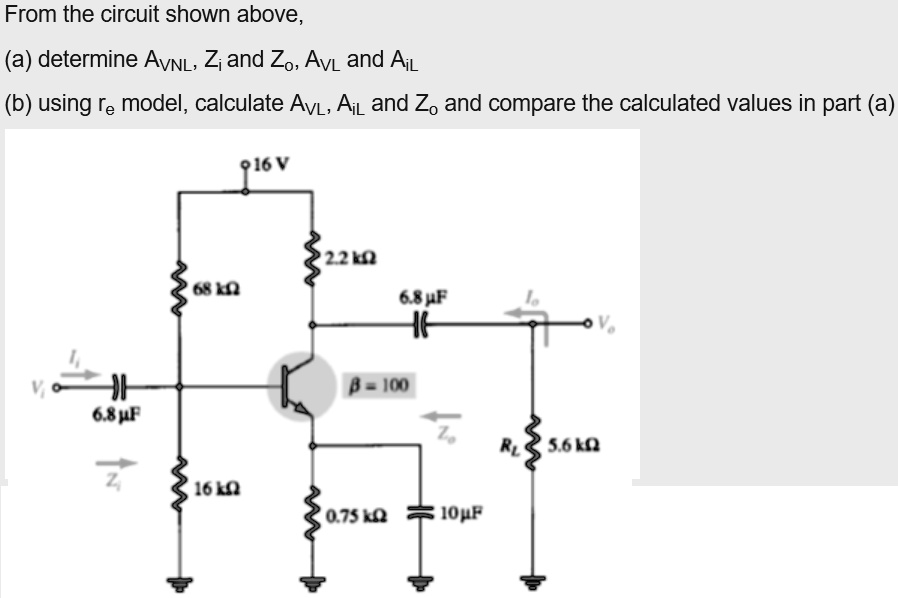
SOLVED: From the circuit shown above, (a) determine AvNL, Zi and Zo, Avi and AiL (b) using the re model, calculate AvL, Ai, and Z, and compare the calculated values in part (
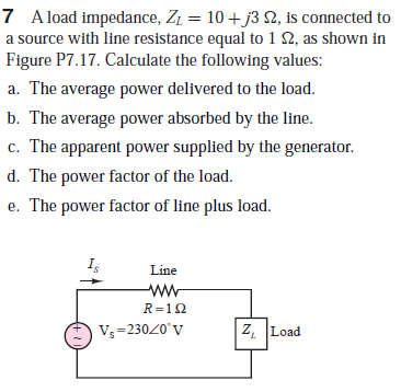
Answered: 7 A load impedance, Z1 = 10 + j3 2, is…
Solution
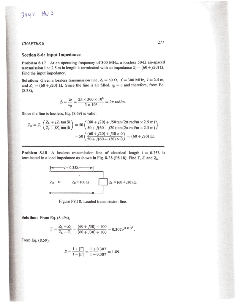
Problem 2.34 A 50-Ω lossless line is terminated in a load impedance

Reflection Coefficient - an overview

For the circuit in Fig, choose the load impedance ZL so that the power dissipated in it is a max